
Heat Pump Retrofits Succeed or Fail on the Controls Sequence
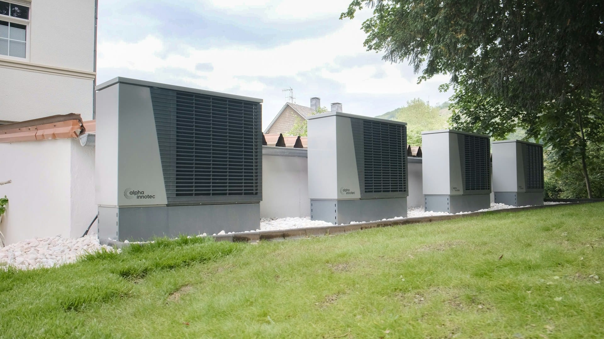
The design calculations on a commercial heat pump retrofit usually look fine. Loads are calculated, the units are sized, the hydronic side has been checked against the existing radiators or fan coils, and the energy model shows a healthy drop in gas use. Then the building runs through its first winter and the numbers come back disappointing. The backup boilers carried more of the load than planned. The heat pumps short-cycled all through the shoulder months. Someone on the facilities team took cold calls from the third floor and bumped the supply water setpoint up by ten degrees, and it never came back down.
None of that is a hardware failure. It is a controls failure, and in my experience it is the most common way these projects underdeliver.
Supply Water Temperature Is the Whole Game
An air-to-water heat pump gets less efficient as the temperature it has to produce goes up. A commonly used rule of thumb is a couple of percent of efficiency lost for every degree Celsius of extra supply temperature, and the gap between running at 45°C and running at 60°C shows up clearly on the electricity bill. Every degree you can take off the supply temperature, for as many hours of the year as possible, is money.
So outdoor air reset is not optional. Many older buildings were designed around 80°C flow and then run flat out all winter, because nobody set up a reset curve or the one that existed was disabled after a complaint. When heat pumps go in, the reset curve has to be real, tuned on site, and protected from casual overrides.
Better still, reset on demand rather than outdoor temperature alone. If the BMS can see valve positions on the terminal units, it can lower supply temperature until the most-open valve is close to fully open, then hold there. That trim-and-respond approach follows what the building actually needs instead of a curve somebody guessed at during design. It also exposes the problem zones quickly. One undersized radiator in a corner office can hold the whole plant ten degrees hotter than necessary. Find that room, fix it, and the entire system benefits.
Staging Heat Pumps With the Existing Boilers
Most commercial retrofits keep at least one of the old boilers, either as backup or to cover peak days. How the two are staged together decides how much gas the building really saves.
The usual mistake is a simple outdoor temperature lockout: below some changeover point, the heat pumps hand everything over to the boilers. It is easy to program and easy to explain. It also throws away all the hours where the heat pumps could have carried most of the load with the boiler only trimming the top.
One Controller Sets the Temperature
A better sequence keeps the heat pumps as lead across every condition they can physically operate in, and brings the boiler on as lag only when the heat pumps cannot hold the supply setpoint after a reasonable delay. The boiler should be piped and controlled to boost the heat pump output, not compete with it. If the boiler sits in parallel and both machines chase the same setpoint with their own controllers, the boiler tends to grab the load because it responds faster, and the heat pumps back off. On a trend log it looks like the heat pumps are working. On the gas bill, they are not.
Put one controller in charge of supply setpoint and plant staging. Usually that is the BMS. The heat pumps and boiler then receive enable and setpoint commands rather than each running independent logic against the same header temperature.
Also check the water returning to the heat pumps. If 70°C boiler water finds its way back to the heat pump inlet through a bypass or a badly placed connection, the units will trip on high pressure or derate themselves, and they will do it on exactly the cold days you need them most.
Defrost Is Predictable, So Plan For It
Air-source units in damp weather near freezing will defrost often. During a defrost cycle the unit reverses and pulls heat from the water loop to clear the coil. On a system with little water volume, supply temperature drops sharply, the BMS sees it, and a poorly written sequence calls the boiler. Then the defrost ends, the heat pump comes back, and now two heat sources are fighting over a loop that did not need help.
Several things prevent this. Enough system water volume, often with a buffer tank, so a defrost does not crater supply temperature. A time delay on boiler staging long enough to ride through a normal defrost. And where the unit exposes it over BACnet or Modbus, a defrost status point the BMS can read, so the sequence knows the dip is expected and leaves it alone. On multi-unit plants, ask whether defrost cycles can be staggered so the units never all defrost at once.
Low-Load Cycling in the Shoulder Season
Heat pumps are usually sized close to peak load, and peak is a handful of days a year. Through long stretches of spring and autumn the building needs a fraction of that capacity. If the minimum compressor output is above the actual load, the unit cycles: on, overshoot, off, drift, on again. Short cycling wears compressors and drags efficiency down.
The controls fixes are mostly about deadbands and runtime. Minimum on and off times, a wide enough differential, and staging logic so that at low load one unit runs properly instead of every unit throttled to its minimum. Buffer volume helps here too. If the plant mixes variable-speed and fixed-speed units, the variable unit should lead at low load. That sounds obvious. I have still found it set up backwards on more than one site.
Integration With the Existing BMS
Many heat pumps ship with a capable onboard controller, and some integrators are tempted to let it run the show and bring a few monitoring points into the BMS. That works for a single unit on a single loop. It struggles everywhere else.
Decide early which system owns which decision. At minimum, the BMS should be able to:
- Enable and disable each unit and write its leaving water setpoint
- Read operating mode, defrost status, alarms, and compressor speed or capacity
- Read entering and leaving water temperatures and, ideally, electrical power
Ask for the integration point list before the units are ordered. A unit that exposes a few dozen useful points over BACnet and one that offers a handful on a basic Modbus map are very different things to integrate, and the time to find out is not after the crane has left. Without power data in particular, nobody can verify the efficiency the project promised.
The Mistakes That Keep Showing Up
Commissioning these systems properly means watching them across a range of conditions, not running one functional test on a mild afternoon. The errors that recur are mostly sequences nobody revisited. A reset curve left at design defaults. A boiler changeover temperature set conservatively warm during startup and never lowered. Terminal unit controls still tuned as if they were receiving 80°C water. Trend logging too sparse to diagnose any of it. ASHRAE Guideline 36 is a sensible reference for structuring hydronic plant sequences, though it needs adapting for heat pump behavior such as defrost and minimum capacity.
The most useful single check is to trend boiler runtime against heat pump runtime by outdoor temperature bin through the first heating season, and sit down with the controls contractor after the first properly cold month. If the boiler is running at outdoor temperatures where the heat pumps should be carrying the load alone, the sequence is wrong, and you now know exactly where to look.